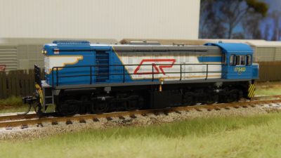
 Here we go again with yet another series of delusional rants from Planet Jandowae.
A small voice in my head (well a Bridget shaped voice in my right ear actually) has been telling me for some time that I need to “get my ****** **** ** ****** (censored for your benefit) *** **** ** ***** into gear and show the installation of a sound unit for a 1720”.
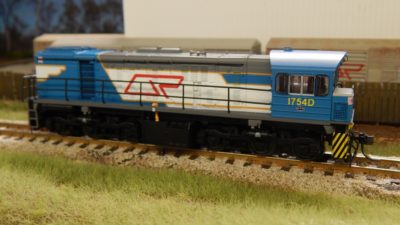 So after having come up with the idea to install one of these decoders all by myself, I have decided (without ANY influence at all) to show you step by step how I install the sound units in my 1720s.
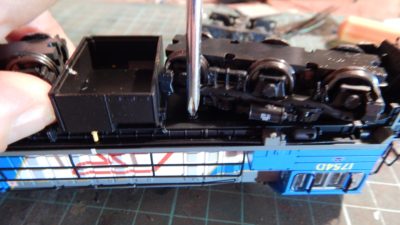 The first step is to remove the shell from the locomotive.
This is done VERY quickly by simply undoing the two small Philips Head screws under the locomotive. They’re diagonally opposed from each other on either end of the fuel tank (the same as they are on all our locomotives). You may prefer to (in standard gauge you will have to) remove the sideframes from the bogies.
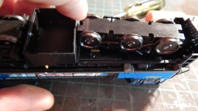 To remove the sideframes, just place a small flat bladed screwdriver behind the sideframe and gently press it out from the two mounting pins. Just place them to one side until you’ve installed your decoder.
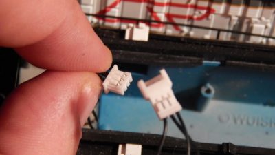 The shell can then be removed from the locomotive. Keep in mind, this is a tight fit and should be removed slowly. DO NOT try to take the shell completely away from the chassis as it is still attached by two sets of three wires. These can be unclipped and this should be done carefully as they are very small clips.
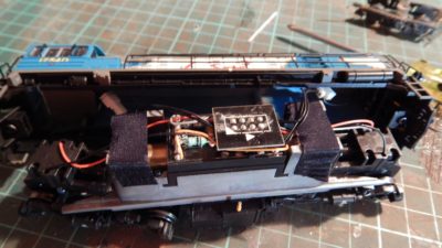 Once this is done, it is simply a case of removing the dummy plug from the printed circuit board. Try to do this with even pressure or pry it up with a small flat head screwdriver.
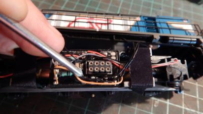 Once the plug is removed, plug in your decoder. Please remember that ALL decoders use the orange wire as PIN 1. Pin 1 on the PCB can be located by a small white rectangle that is printed around the socket. There is a triangulated corner of this white rectangle… This is pin 1. So ensure the orange wire is plugging into pin 1.
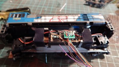 If you’re just fitting a standard DCC decoder, this is all you need to do aside from poking the decoder inside the shell (above the lights wires on the hood end will keep everything in position) and reattach the shell to the chassis. If you’re fitting sound, keep reading.
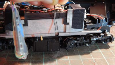 When fitting the sound unit, you will notice that there is a pair of brown wires coming from the decoder. These are the wires for the speaker. If you look at the chassis, you will note a small indented section leading to the fuel tank on one side. This is where the wires feed through to the speaker enclosure.
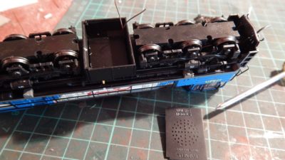 The speaker enclosure is located inside the fuel tank. Under the model, you’ll see a flat speaker plate with holes in it (as well as some strange words such as “Wuiske” no one is really sure what these mean). This plate can be removed with a small flat screwdriver blade in one end of the tank.
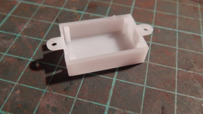 Once you can see inside the tank, pass the two brown wires through the opening into the fuel tank and you’re ready to attach the speaker. DO NOT use the white (or black) baffle box that is included with the speaker as it is taller than the fuel tank (It’s a 1720, they’re small).
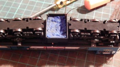 Carefully solder the wires to the speaker terminals. It does not matter which wire is soldered to which terminal. At this point, I usually place some Play-Doh in the bottom of the speaker enclosure before pressing the speaker inside. This will eliminate any negative sound from leaking…
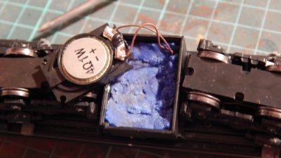 Negative sound is where you have sound vibrations emanating from both sides of the speaker. If they meet, they cancel each other out. This will result in a very quiet sound that has little bass and sounds distorted.
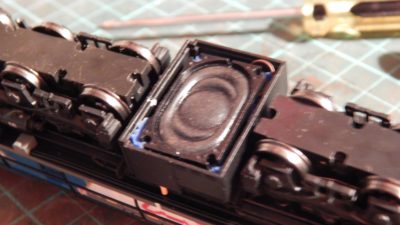 Next I press the speaker into the Play-Doh. Ensuring the speaker is seated nicely inside the fuel tank, I can then refit the speaker plate to the fuel tank. Once this is done, simply reattach the shell and the locomotive is done.
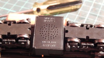 The final step is to program the running number. Prior to this though, I suggest test running the locomotive with the default address of 03. This is done merely as a possible fault finding step later on if problems occur. But I will mention this in a minute.
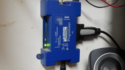
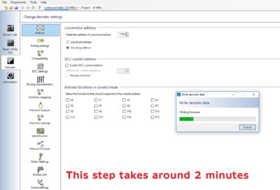
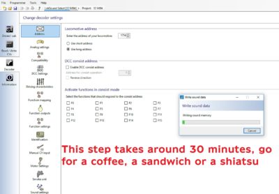
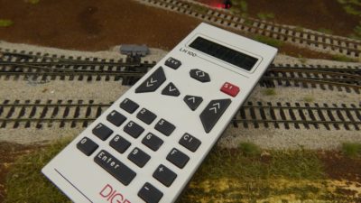 Programming the running number is done in a number of different ways, depending on which DCC system you’re using on your layout. I have the Lenz system using LH-100 controllers and it is a simple case of placing the locomotive on the programming track and pressing button F (function), 8, then entering the running number and pressing ENTER. That being said, I nearly always program my locomotives using the Loksound Programmer which is mounted to the wall next to my computer.
 I mentioned earlier “fault finding”. This is something I have learnt to do every step of the way. As a manufacturer, I get calls from people whom claim to have a “dud” locomotive. Nine times out of ten, it is actually the fitting of the decoder that has been done wrong and could have been avoided. So, here’s what I do for my own locomotive fleet.
 First and foremost, I run the locomotives in using just DC. Running in is ESSENTIAL as these are a mechanical device and they have gears and bearings that need to bed in (just like with a car or motorcycle). I usually let mine run for about an hour in each direction at top speed. Then I knock them down to about half speed and allow them to run for a few hours in each direction. You’ll notice that this will remove any wobble and excess noise from the models.
 This step also means that I can eliminate the locomotive being the issue if it does not work once I have installed the decoder. The next step is to run it with the decoder installed BEFORE I have programmed it. This means that if it has an issue once I have programmed it, then the fault lies with something I have changed by accident in the programmer.
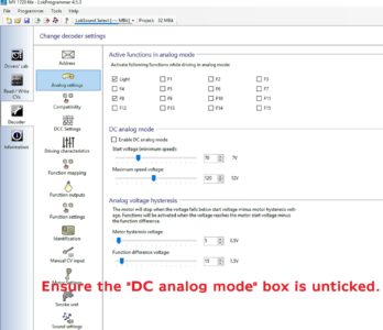 One thing I do HIGHLY recommend is to turn off the DC function on your decoders. This can easily be done with the programmer but can also be done with the controller on your DCC system. I suggest this as I had a wiring fault on my layout a couple years ago that was burning out decoders. The fault was caused by the AC current coming from the DCC system being blocked and only a low voltage DC current getting through on one section of the layout.
 As a result, the locomotive (only two locomotives did this too, the rest were fine) would go quiet and then crawl along as it was trying to switch from AC to DC and back constantly for a while. This killed two decoders on my layout and also took me a few months to find the cause of.
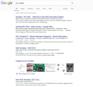 The end result, was I fitted a “Snubber” to the layout in each power district and the problem was solved. I would suggest looking up a DCC filter or Snubber on google and seeing what you come up with as this VERY cheap fix has saved me a lot of headaches and has meant that I swear a little less.
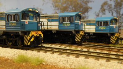
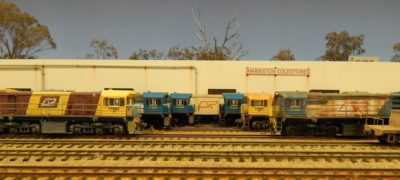 So with 1754D added to my fleet, she is ready for weathering. When I installed the decoder in this locomotive I also installed two others. So my 1720 fleet is now sitting at 6 locomotives. The goal is ten, not for any special reason except that when I was a kid, I said I would love to be able to have ten 1720s on my layout.
As always though, we shall see how we go.
